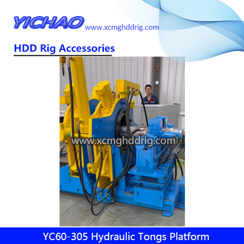
The hydraulic tongs platform is a critical device for thread connections in various petroleum geological drilling tools, tubing strings, and downhole equipment. Our YC60-305 model, developed by integrating advanced foreign technologies with China’s petroleum industry characteristics, stands as the industry leader among domestic counterparts.
2.Technical parameters
motor system
power
18.5KW
revolving speed
1470r/min
hydraulic system
fuel tank capacity
0.5CM3
system pressure
Max.working pressure 16MPa
suitable workpiece pipe diameter range
Φ60—305mm
fixed snap system
Six-cylinder clamping speed
0.6m/min
Six-cylinder synchronization accuracy
5%
one shot angle
>36±2°
reciprocating stroke
5 times/min
activity clamp system
rated clamping force
5KN-295KN
Six-cylinder synchronization accuracy
5%
travel distance
2.7 m
travel speed
0-8m/min
tailstock push-pull system
length of workpiece pulled
0-3m (adjustable)
cylinder stroke
2.0m
cylinder speed
0-6m/min
Max. pulling force of hydraulic cylinder
180KN
Max. pushing force of hydraulic cylinder
240KN
quick coupling system
suitable pipe diameter
Φ60-Φ305mm
threading torque
4KN.m
Hydraulic support brackets (2 front units, 1 rear unit, 3 units in total)
support load
5T
support diameter
Φ60mm-Φ305mm
bracket center height can be adjusted
190mm
3.Each part structure and working principle
1.Structure
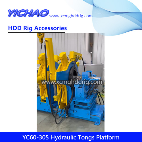
YC60-305 hydraulic disassembly frame consists of two main components: the hydraulic disassembly frame operating platform and
The hydraulic disassembly frame operating platform is mainly composed of oil tank, motor, plunger pump, vane pump, various valves, instruments, pipe fittings, etc. The hydraulic disassembly frame operating platform can control the actions of the hydraulic disassembly frame main body through the operating handle on the hydraulic disassembly frame operating platform.
The hydraulic disassembly frame is composed of fast rotating mechanism, tail frame push-pull mechanism, walking clamping mechanism, fixed clamping mechanism, base and hydraulic support frame. The functions of fast rotating, clamping, unclamping and axial push-pull are realized by the coordinated action of each part.
The system has high precision torque measurement system, which can accurately collect the torque in the process of screwing and display it in real time on the human-machine interface. It has the functions of recording, data and curve storage, printing and output. 2.Working principle:
The YC60-305 hydraulic disassembly frame is powered by an electric motor driving a plunger pump and a vane pump. It features independently controlled clamping and loading/unloading mechanisms, with a pressure range of 0-16MPa. 1.fixed clamp:
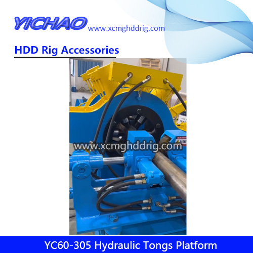
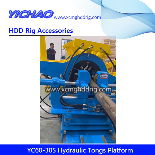
The fixed clamping device is used as a fixed jaw, which consists of a six-cylinder clamping device and a six-cylinder synchronous valve, and it clamps the workpiece under the action of six hydraulic cylinders at the same time.
2.Clamping system
The system consists of three components: clamping, punching, and travel mechanisms. Its clamping principle is identical to that of fixed clamping pliers. The punching section utilizes hydraulic power to control the reciprocating motion of the punching cylinder, enabling precise fastening and unfastening operations. This design supports high-torque rotational punching and heavy-duty pushing/pulling tasks. The rotary mechanism with bearing-connected components allows the equipment to generate substantial fastening/unfastening torque even under low pressure, minimizing energy waste from high-pressure conditions while preventing hydraulic system leaks. Simultaneously, the hydraulic motor drives gears, enabling the six-cylinder clamping pliers to move reciprocally along the worktable’s axis (i.e., the workpiece’s longitudinal direction), thereby adjusting the workpiece’s axial position.
3.Quick coupling system
The quick-rotation mechanism is connected to the punch walking clamp, utilizing a suspended gantry for automatic centering, single-cylinder clamping, and four hydraulic motors to drive the four friction wheels. This enables the drill string to achieve rapid thread engagement. It features simple operation, wide application, and exceptional mobility. Its most distinctive characteristic is the high torque, allowing automatic position adjustment according to the workpiece’s concentricity.
4.Tailstock push-pull system
The section is designed according to the structure of the equipment of U.S. Smith company, which can walk on the 8-meter-long track, pull the hydraulic cylinder, and disassemble and assemble the long tools such as the screw drill through the operation of the mechanical and hydraulic parts. The tail frame is pushed and pulled automatically by the traction of the hydraulic motor.
5.Hydraulic support (2 front, 1 rear, 3 units in total)
The hydraulic support moves along the axial direction of the main engine in both forward and backward directions.
6.Hydraulic control console
This system employs internal control with console operation, connected to the main unit via hydraulic pipelines. The control console houses a series of hydraulic components including multi-way directional valves, all featuring high-quality multi-layer high-pressure rubber hoses at their inlets and outlets to prevent internal leakage. The operation handles of the multi-way directional valves are all mounted on the console surface, with clear and intuitive labeling for easy operation.
4.Installation and debugging
1.Install
Connect the workbench and the disassembly frame according to the hose specifications and markings. (Note: Keep the hose clean during connection, avoid oil contamination, and do not pull the hose too tight.)
Fill the tank with filtered 46# wear-resistant hydraulic oil, and check the oil level to ensure it is as full as possible.
Connect the power supply to the control panel (three live wires, one neutral wire, and one ground wire). After powering on, check the motor rotation direction (rotate clockwise as indicated by the plunger pump arrow). Note: The pump located below the computer is a plunger pump. 2.Debugging
1.After the device is assembled as per the instructions, double-check that all piping connections are properly secured.
Start the motor. If no abnormal noise is heard, run continuously for 15 minutes and check the operation table pipeline for leaks.
2.To adjust the system pressure, push the tailstock’s moving lever to set the pressure regulator valve to 16MPa (The system pressure is preset at the factory). The maximum pressure must not exceed 20MPa.
The quick-rotating clamping cylinder, quick-rotating screw motor, tail frame push-pull cylinder, tail frame moving motor, punch-closing cylinder, clamping cylinder, punch-closing moving motor and support cylinder are tested respectively. They are reciprocated 3-5 times under no load.
The clamping cylinder synchronously adjusts the oil cylinder’s one-way throttle valve. After adjustment, lock the spare valve above the one-way valve to prevent flow instability.
5.Operation and usage
1.reparatory work
Check the fuel gauge and all connection points for looseness or leaks.
Before startup, all control handles are set to the middle position, and the pressure regulating valve is at its lowest position.
Start the hydraulic pump and run it unloaded for a few minutes to check for any abnormalities. Then operate the directional control valve and pressure regulator to align the instrument readings with the torque requirements of the workpiece mounting frame.
2.Uploading operation
Firstly, the workpiece is lifted by the crane and sent into the jaw of the fixed clamp from the tailstock. Then, the workpiece is pushed slowly into the jaw. After the workpiece enters the jaw, the clamping cylinder is used to secure it.
The workpiece clamped by the fixed clamp is slowly sent into the quick coupling by moving the clamping tool, the distance between the workpiece and the quick coupling is adjusted, then the workpiece is clamped by the quick coupling hydraulic cylinder, the quick coupling motor is started, and the workpiece is spun together until the quick coupling motor slips.
Adjust the upper tightening torque by operating the clamping cylinder handle. Then, move the clamping tool to position the workpiece’s threaded section into the tool’s jaws. The clamping cylinder secures the workpiece, initiating the tightening process. Once the clamping cylinder reaches its full extension, release the workpiece and return the clamping cylinder to its original position. The clamping cylinder then engages to continue tightening. Repeat this cycle until the target torque is achieved.
3.Download operation
1.The way of workpiece feeding and preparation is the same as that of the upper buckle.
2.Move the punch clamp to gently guide the workpiece held by the fixed clamp into the punch jaw. The clamping cylinder then secures the workpiece, initiating the unclamping process. Once the punch cylinder reaches its target position, release the workpiece from the clamping cylinder, then return the punch cylinder to its original position to allow the clamping cylinder to re-secure the workpiece, continuing the unclamping cycle. Repeat this sequence until the unclamping torque drops below 1MPa.
3.When the unfastening torque drops below 1MPa, switch to a quick-release tool until complete disengagement.
4.If the workpiece fails to disengage or slips under the preset torque, increase the torque and clamping force to complete the disengagement.
4.Tailstock push-pull device operation:
Move the push-pull device to the right position, insert the locating pin into the locating hole of the tailstock, and screw the workpiece to be pushed-pulled together with the headstock.
The workpiece is clamped by the fixed clamp, and the axial force is applied to the workpiece by the push-pull cylinder.
5.When the workpiece is lifted to the support roller by the crane, the operator raises the support by operating the corresponding handle on the operating table, so that the workpiece is lifted to the center of the fixed clamp and the punch clamp. If the workpiece has already exceeded the center line, the operator lowers the support by operating the corresponding handle, so that the workpiece is lowered to the center of the movable clamp and the punch clamp.
6.Matters need attention
Do not activate the clamping cylinder without holding any workpiece.
1.When disassembling high-torque workpieces, all personnel except the operator must stay away from the workpiece.
2.When replacing the tooth block of the clamping cylinder, push or pull the piston rod to the appropriate position and then stop the machine. Do not operate any handles during the replacement.
3.The diameter and wall thickness of the workpiece should be taken into account when clamping, and the clamping force should be adjusted in time.The thin-walled workpiece should be clamped at the wall thickness.
4.The surface hardness of the workpiece’s reinforced area must not exceed that of the tooth block, otherwise it may cause slippage or damage to the tooth block.
5.The system pressure must not exceed 20MPa, and the hydraulic motor pressure must not exceed 10MPa.
6.No items shall be placed on the workbench during the movement of the clamping pliers and tailstock push-pull device.
7.The workpiece should be gently placed into the jaws, not forcefully.
7.Maintenance and care
1.Contamination must not enter the oil system. When refueling the tank, clean all service tools and replace the oil periodically as needed. Typically, oil should be changed after 1,000 cumulative operating hours, or every six months to one year depending on usage. During oil changes, thoroughly clean the tank bottom of accumulated contaminants using cleaning oil or kerosene, wipe clean with cotton cloth, and dry with compressed air. When filling the tank, use an oil filter with a mesh size of 120 or higher.
2.It is forbidden to let water enter the hydraulic system. Otherwise, the oil will be emulsified, the lubrication and sealing of the oil will be reduced, the hydraulic oil will be aged prematurely, the service life of the pump, valve and other components will be reduced, and the leakage will be increased.
3.Check the pressure gauge regularly to prevent errors and reduce accidents.
4.If the system pressure is unstable, abnormal noises or cylinder crawling occur, the machine should be stopped immediately for inspection and maintenance.
5.Regularly inspect all seals for leaks and address any issues promptly.
6.Check for abnormal noises in all moving parts, and if any, inspect and repair them promptly.
7.Monitor the oil temperature, which must not drop below 15℃ when starting the machine, and must not exceed 60℃.
8.Check the wear of the tooth block and replace it in time after wear.
9.Apply grease to exposed parts regularly to prevent rust.
10.Lubricate the relevant parts as shown in the table below