Categories
Latest Updates
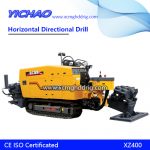
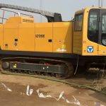
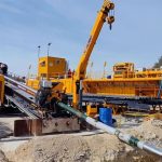
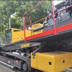
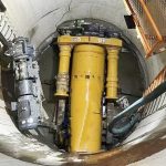
The spiral pipe jacking machine is a kind of equidistant spiral rod for mud discharge of roadheader head, including a cylinder, a spiral rod, a spiral vane group fixed on the spiral rod and a mud discharge pipe. The cylinder and the mud discharge pipe are sleeved outside the spiral vane group. The spiral vane group includes several spiral vanes with the same diameter and equidistant arrangement. One end of the spiral rod is close to the power source and installed on the main shaft of the power source, and the other end is connected with a joint, The utility model can connect multiple spiral rods, extend the length of the spiral blade group and the mud discharge pipe, and facilitate the long-distance transportation of soil.
The construction process of the above spiral pipe jacking machine includes the following steps:
First, carry out pre construction preparation, then install the guide rod, install the mud discharge pipe, install it into the head of the tunneling machine, and finally push the cement pipe.
This construction method provides a spiral pipe jacking machine and its construction technology, which can solve the problem of mud clogging the mud discharge pipe. This construction method requires less manpower and material resources, and has no great impact on transportation. It saves material input, saves construction period input, and indirectly saves a lot of economic input.
Install the probe into the probe chamber of the guide drill bit and calibrate the parameters or install the laser guide drill bit. Install the O-ring on the male joint of the guide drill pipe, connect the guide drill pipe with the male and female of the guide drill bit, tighten and lock them with the hexagonal socket screws, operate the control valve of the main jacking cylinder, and fix the power box to a slot behind the cylinder with a clamp.
Then install O-ring on the main shaft of the power box, connect the guide drill pipe with the male and female of the main shaft, connect the grouting pipe to the rear water joint of the power box, operate the rotary control valve, the guide drill bit rotates, operate the jacking oil cylinder control valve, and the guide drill bit starts to rotate and jacking. With the jacking of one guide drill pipe, control the depth and direction of the guide drill bit drilling under the guidance of wireless guider or laser, and drill a pilot hole at the set location, At the same time, the guide bit stretches out in the receiving well and is removed, that is, the guide drilling is completed.
Return the power box to the rear clamping slot of the oil cylinder and fix it with the clamping plate. Install the top mud discharge pipe seat at the front of the power box and fix it with eight hexagon bolts. Install the transition joint of the mud discharge pipe at the female joint of the guide drill pipe, tighten and lock it with the hexagonal socket screws, connect the mud discharge pipe with the transition joint through the taper tooth, operate the oil cylinder control valve, and move the power box forward to enter the top mud discharge pipe seat and move forward with the oil cylinder, The mud discharge pipe is jacked into the pilot hole, and the transition joint of the mud discharge pipe of the receiving well is exposed. Remove it, and the process is completed.
Install the screw rod transition joint on the main shaft of the power box, tighten and lock it with high-strength socket head cap screws, then connect the screw rod with its transition joint, tighten and lock it with high-strength socket head cap screws, operate the oil cylinder control valve, push the front end of the screw rod into the mud discharge pipe, push it in one by one, and finally extend the screw rod from the mud discharge pipe at the receiving well. At this time, the screw rod has been installed, The butt joint of each screw rod is required to be secured and locked with high-strength socket head cap screws.
First, connect the pressure oil pipe, drain oil pipe, water pipe and grouting pipe on the motor of the roadheader head, connect the screw rod with the male female joint of the main shaft of the roadheader head, then tighten the screw to lock it, remove the top mud discharge pipe seat at the front end of the power box, install the top cement pipe seat, and then operate the oil cylinder valve to push the top cement pipe seat into the head support. With the head moving forward, the front butt joint of the head is connected with the mud discharge pipe, Hold the tail end of the mud discharge pipe and the connecting pipe at the front end of the head with a hoop, lock it tightly with four socket head cap screws, operate the rotary valve, rotate the screw rod, operate the oil cylinder valve, move the head forward and jack it into the soil, and the screw rod will gradually discharge the soil cut by the heading machine head to the receiving well. With the head jacking, this process is completed.
Insert the front end of the cement pipe into the tail end of the machine head, operate the oil cylinder valve, push the top mud discharge pipe seat into the tail end of the cement pipe, operate the valve, monitor the rotary pressure and jacking pressure on the foundation pit equipment, control the jacking speed, start the water pump when the second cement pipe is jacked in, inject water into the mud discharge pipe, push the third cement pipe, start the grouting pump, and inject mud into the head shell and cement pipe shell, As the cement pipes are jacked in one by one and the mud discharge pipes and screw rods of the receiving shaft are removed one by one, the tunneling machine head is finally jacked out of the receiving shaft, the tunneling machine head is removed, and the soil of the receiving shaft is transported away. The whole construction is completed.
Difference between spiral pipe jacking machine and slurry balancing machine
When the pipe diameter is less than 4800mm and the geological condition is high cohesive soil, the jacking construction method of spiral pipe jacking machine is less difficult than the traditional “slurry balanced pipe jacking” method.
The construction time is reduced and the construction efficiency is improved. The slurry balanced pipe jacking machine is easy to get stuck in the high cohesive soil geology, which affects the construction progress. The spiral pipe jacking machine can just solve this problem and accelerate the construction progress. The discharge of slurry from pipe jacking is reduced, causing less pollution to the city, reflecting the operability of the construction site. The construction is more standardized, safer, and more controllable. The site shutdown caused by mechanical failure and external factors is reduced, which improves the construction efficiency and shortens the construction time.
