Categories
Latest Updates
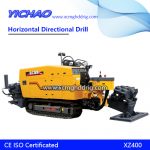
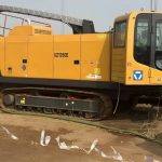
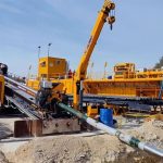
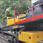
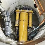
With the wider application of trenchless horizontal directional drilling technology, there are more and more difficulties encountered in the construction of directional drilling. At present, most of the small drilling rigs used in the market use wireless positioning technology during the construction of pilot holes. This paper briefly introduces the design method of the pilot hole trajectory during the construction of wireless positioning technology.
The engineering survey work in the early stage of the construction of the trenchless horizontal directional drilling pilot hole is a crucial step. The survey content includes four aspects: 1. Topographic survey; 2. Exploration of background noise; 3. Engineering construction requirements; 4. Original There is pipeline detection. Among them, the construction requirements and the original pipeline detection are the keys to provide the basis for the design of the pilot hole trajectory.
1.1 Topographic survey
Topographic survey is one of the tasks that must be done before the design of the pilot hole trajectory. The purpose is to find out the width of the river on the construction line, the depth of the deepest part of the river bed, the height difference between the two banks, and the visibility between the excavation point and the earth entry point.
A detailed understanding of the buildings, structures and river water velocity on the ground should be made. At the same time, a detailed understanding of the underground concealed works on the construction path should be made to clarify their buried depth, distribution location and the degree of influence on the guiding construction.
1.2 Background noise
Background noise refers to interference signals and interference sources that affect the locator reading and measurement accuracy during construction. Background noise is generally divided into two categories: one is a spontaneous interference source, that is, it can emit interference signals to affect the locator; the other is shielding, which interferes with positioning by blocking the signal transmission of the locator instrument.
These two kinds of noise have a particularly great influence on the instrument reading during the construction of the pilot hole, so it must be investigated clearly before the trajectory design. For example: electric cables, telephone cables, street light wires, steel bars on the road, river water with high salt content, etc.
1.3 Engineering Requirements
The requirements of the trenchless project are the embedding depth of the two ends of the pipe head, the length of the pipeline, the slope of the pipeline, the embedding depth of the river bottom crossing the river and the plane position of the engineering pipeline when the Party A drags and lays the pipe back according to the engineering use requirements or the engineering construction drawings. Require. The relevant engineering technical requirements should be completely clear before the pilot hole trajectory design.
1.4 Pipeline positioning
Before designing the guide hole trajectory, all-round detection of the original pipelines on the construction path should be carried out to clarify the direction, depth, and spatial relationship between each pipeline and the pipeline to be laid. Pipeline detection is generally divided into four parts: one is to classify and mark the pipeline signs that can be seen by the naked eye, and directly measure the depth and direction of engineering pipelines that can be directly revealed; the other is to use pipeline detection for outcrops of special pipelines The instrument is used to locate it; the third is to use the instrument to scan and locate the pipeline that has no outcropping but actually exists. For the existing pipeline at the bottom of the river, its corresponding engineering drawings shall be adjusted to confirm its depth and direction. Finally, a comprehensive underground pipeline distribution map is drawn according to the relevant positions of the pipelines.
Plane positioning is to draw up the horizontal trend curve of the drilling trajectory in the field according to the relative position of the original pipeline and the pipeline to be laid before the pilot hole trajectory design, and then set some control points on the curve. The control point should be selected at the part where the proposed trajectory curve and the original pipeline intersect. When the proposed trajectory is parallel to the original pipeline, the control point should also be set at the part where the horizontal distance is less than 1 meter. These control points provide a reference for the horizontal position and depth during pilot hole construction.
When the proposed trajectory crosses the river, a control point should be set every 3 meters within 15 meters on both sides of the river bank, and try to ensure that the 15 meters are a straight line to create a favorable drilling trend for the pilot bit to enter the river bed. After all the control points are set, draw a plan of the control points to provide a design basis for the subsequent trajectory design.
2.2.1 Calculation of the minimum bending radius R of the pipe and the curvature α1 of the drill pipe
The curvature of the pipe is an important basis for the trajectory design. An important indicator of the curvature of the pipe is the minimum bending radius R of the finished pipe. In the process of trajectory design, the bending radius R1 of each arc segment should be larger than the minimum bending radius of the pipe (R1>R) , but the curvature of R1 should be smaller than that of the minimum bending radius R2 of the drill pipe (R1>R2). These are two necessary conditions for pilot hole trajectory design.
Usually, the manufacturer has calibrated the value of R2 before leaving the factory, and calculated the limit curvature α of each drill pipe according to this value. Therefore, the bending radius of the pipe and the conversion rate of each drill pipe during construction should be determined before the trajectory design, which can be calculated by the following formula:
1. Calculation formula of the minimum bending radius R of the pipe
R=(r×E)/σ
r—the radius of the pipe
E—the elastic modulus of the pipe material
σ—Yield strength of pipe material
2. Calculation formula of curvature α1 of each drill pipe
α1={2×R×SIN2((L×180)/(л×R))}/3
R—minimum bending radius of pipe
L—the length of each drill pipe
л—pi ratio
2.2.2 Selection of entry angle A and unearthed angle B
The selection of the angle of the entry angle should be determined according to the size of the retreat distance, the range of the angle change of the drilling rig, the size of the site where the drilling rig is placed and the material of the engineering pipe. Generally speaking, the angle of drilling rig into soil is proportional to the angle change range of the drilling rig itself, inversely proportional to the site where the drilling rig is placed, inversely proportional to the radius of curvature of the engineering pipe, and inversely proportional to the retreat distance. When selecting the entry angle, first consider the radius of curvature of the engineering pipeline and the size of the retreat distance, and secondly consider the size of the entry site and the angle range of the drilling rig itself.
The excavation angle should be determined based on the length of the excavated slope section, the curvature radius of the engineering pipeline, the size of the work site of the excavation pit, and the buried depth of the original underground pipeline. The size of the excavation angle is inversely proportional to the above factors, but the length of the build-up section and the radius of curvature of the engineering pipeline are the preferred considerations.
2.2.3 Calculation of the minimum retreat distance L1
The retreat distance is the horizontal projection distance from the deepest point of the proposed drilling curve to the drilling rig entry point. The calculation first considers the deepest or shallowest pipeline depth on the drilling trajectory line, the maximum buried depth of the building foundation, and the riverbed depth of the surface river, and determines the maximum control of the steering trajectory according to the above conditions and the buried depth requirements of the engineering pipeline. Depth H1, the minimum length from the deepest point to the drilling point is the minimum retreat distance L1.
When calculating the minimum retreat distance, the drilling angle A, the depth H2 of the drilling point, the curvature of the drill pipe, the depth of each control point, etc. should be comprehensively considered. In the calculation, the length within each two control points is used as the calculation control unit, and each drill pipe is used as the calculation unit. The calculation can be verified by the following steps:
Depth of the first drill pipe: H2 (depth of drilling point)
The depth of the second drill pipe: H2+L×A
The depth of the third drill pipe: H2+L×A + L×(A-α1)
And so on until the depth is the control depth H1 of the deepest point. Then multiply the number of drill rods reaching this depth and multiply the length of each drill rod to obtain the minimum retreat distance L1.
Drawing the curvature change and the corresponding depth of each drill pipe into a graph is the design curve of the pilot hole trajectory.
2.2.4 Trajectory design requirements
The trajectory design should meet the following requirements:
1. The designed trajectory length should be consistent with the length of the engineering pipeline shown in the engineering requirements (except for sewage pipes);
2. The depth of the guiding track is consistent with the buried depth of the engineering pipeline;
3. The radius of curvature of each curved segment of the track should be greater than the minimum bending radius of the engineering pipeline;
4. The horizontal direction should be consistent with the direction of the control point, and the horizontal deviation is less than or equal to 1 meter;
5. Except for the information pipeline, there shall be no undulating sections in the trajectory of other engineering pipelines;
6. For crossing signal interference areas or river courses, the trajectory should be designed as a horizontal section as much as possible;
1. Correct understanding of engineering requirements is the premise of guide hole trajectory design.
2. Identifying underground pipelines and engineering obstacles is an important basis for trajectory design.
3. Correct calculation of engineering parameters is the key to the success or failure of a project.
According to the existing construction methods, it is impossible to accurately guide and locate the areas with strong construction interference.
