Categories
Latest Updates


The project laid a 63m long, 24-hole telecommunications pipeline in a certain city. This road has a large traffic volume, the road is concrete, and the thickness is about 30cm. Below the concrete cushion, the thickness of the miscellaneous fill is not large, mainly the Quaternary soil layer, and the stratum is rich in water content. As there are sewage pipes and water pipes within 4m below the ground surface, the trenchless pre-pipe technology is used to lay Ф1000mm×12mm steel pipes at a buried depth of 5.5m as the protective pipe. Manual excavation in front of the pipe and mechanical pipe jacking are adopted. Lay the steel pipe, and then lay the 24-hole plastic corrugated pipe inside the steel pipe.
The pipe jacking method relies on manual or mechanical excavation of earth at the inner end of the pipe, and then uses jacking equipment in the working pit to jack the laid pipe according to the design centerline and elevation requirements.
The pipe jacking process is a complex mechanical process involving many disciplines such as material mechanics, rock and soil mechanics, elastoplastic mechanics and so on. But the fundamental problem of pipe jacking force calculation is to estimate the thrust and back bearing capacity of the pipe jacking. The thrust during pipe jacking is the resistance of the pipe during the pipe jacking process, including the normal stress of the tool pipe cutting soil, the friction resistance of the pipe wall, and the cutting force of the tool pipe welding joint on the soil layer.
The normal stress of the pipe cutting soil is related to the compactness of the soil layer, the water content of the soil layer and the soil excavation condition in the pipe, and it is usually calculated by the following formula:
fk=25π(D2-d2)k₁
Where: fk——positive resistance of the jacking pipe, kN; D——outer diameter of the jacking pipe, m; d—the inner diameter of the jacking pipe, m; k₁—the positive resistance coefficient of the jacking pipe, kg/m2.
According to the relevant engineering statistics, the soft soil layer is generally k₁=200~300kN/m2, and the hard soil layer is generally k₁:=300~600kN/m2. At this time, k₁=500kN/m2, and fk=89kN is calculated.
The force that the pipeline receives during the jacking process is not only related to the coefficient of friction between the pipe wall and the soil, but also to the magnitude of the earth pressure. And it is related to the degree of bending of the pipe during welding. Because the welding between the pipes is perpendicular to the axis of the pipe, the angle α between the pipe axis and the horizontal line is a slight angle, which can be ignored. The thrust between the pipes is considered to be transmitted in the horizontal direction, which is required The total top force is:
Q=fγ+fk
Where: fγ——total frictional resistance of the sidewall of the jacking pipe, kN, f₁=πDLk₂; k₂——coefficient of frictional resistance of the sidewall of the jacking pipe, kN/m2; L——length of the jacking pipe, m; D——outside of the jacking pipe Diameter, m.
According to relevant engineering statistics, k₂ is generally 5~10kN/m2. Since the cutting effect of the tube wall bending on the soil is ignored, the maximum value = l0kN/m2 is taken at this time. It can be calculated that fγ=1980kN, so the total pre-force is Q=2069kN.
The usual measures to reduce the frictional resistance of the pipe wall are: adding a mud sleeve between the pipe wall and the soil to reduce the drag, the outer wall of the pipe has a regular shape and the surface is smooth, and the pipe bends are reduced.
The back is compressed under the action of the top, and the compression direction is opposite to the direction of the top force. When the jacking stops, the jacking force disappears. When the pipe is jacked, the back should not be damaged and unallowable compression deformation (the back should not be unevenly compressed up and down or left and right), otherwise, the jack is supported on the soil on the back of the slope, causing jacking deviation. In order to ensure the jacking quality and construction safety, the strength and stiffness of the back should be calculated.
As the supporting structure of the jack, the back must have sufficient strength and rigidity, and the compression deformation must be uniform. During the pipe jacking process, the back pressure is much larger than the allowable bearing capacity of the soil wall. Generally, the bearing capacity of clay and silt soil can be calculated as the bearing capacity ≯150kPa. For the sake of safety, take σ=150kPa, and calculate the force area of the back based on the total jacking force required for jacking, so that the force per unit soil of the soil wall is less than the allowable bearing capacity of the soil:
S=Q′σ≈14m2
In the formula: S is the pressure-bearing area required for the back, m2; Q-the total jacking force, kN; σ-the allowable bearing capacity of the soil wall, kN/m2.
In this project, large steel beams and steel plates are used to strengthen the back, and sand bags or gravel are filled behind the section steel to increase the total bearing capacity of the soil wall on the back to meet the top force requirements.
The basic process of pipe jacking construction is: measuring and setting out → making pre-pipe work pit → setting platform → installing back → laying track → jacking pick, jacking iron, oil pump in place → re-measurement of elevation and center line → installing steel pipe → opening Earthwork before pipe excavation → jacking → re-testing, the center line of the bridge front pipeline → backfilling of the working pit.
According to the pipeline layout, inspection wells, topography and surface building distribution, this project will set up 1 pipe jacking work pit and 1 receiving pit. The working pit is determined to be 4m×4mx6m, 1m*lm*1m welding working pits are set on both sides of the bottom of the pit, and a water collection pit is set in the pit. The work pit foundation uses gravel track bed, the thickness of the track bed is ≥350mm, the sleepers are installed, and the sleeper specifications are 150mm×200mm×2500mm, and the spacing is 500mm to prevent the sinking of the work pit and cause the deviation of the jacking position.
The track adopts 38kg/m heavy rail, one on the left and the right, the length of the rail is 6m, and the height of the rail is 134mm. The bottom of the steel pipe is set at 40mm from the top of the sleeper, and the gauge is 392mm. Due to the limitation of working space, the length of each section of steel pipe is 2.0m.
The steel pipe in this project is only used for construction safety protection, so special anti-corrosion treatment is not necessary.
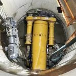
Jacking equipment mainly includes jacks, high-pressure oil pumps, jacking irons, tool pipes and earth-moving equipment. Jack is the main equipment for tunneling and jacking. According to engineering theoretical calculations and actual conditions, the jack used for this project is 300t (3000kN).
The tool tube is the guide head, also called the shield head. The guide head is a section of steel pipe made of steel coils, and the soil is directly excavated and transported manually in front of the guide head.
After the equipment is installed in the working pit, the excavation and jacking can be carried out after checking that all parts are in good condition.
Digging in front of the pipe is the key to ensuring the jacking quality and the safety of the above-ground building. The direction and shape of the excavation in front of the pipe directly affect the accuracy of the jacking pipe position, because the pipe follows the already dug in the jacking process. The earth wall is advancing. Therefore, over-excavation around the pipe should be strictly controlled. For dense soil, it is better to leave a gap greater than 1.5 cm above the pipe end to reduce jacking resistance; over-excavation is not allowed within the central angle range of 135° at the bottom of the pipe end to keep the pipe The wall is flat with the soil wall, and it is also possible to leave a 1cm thick soil layer, which is cut off during the pipe jacking process, so as to prevent the pipe end from sinking. When jacking is not allowed in the section where the soil on the upper part of the pipe jacking is not allowed to be jacked, the pipe shall not be over-excavated.
The digging depth in front of the pipe is generally equal to the length of the jack and the pick, if the soil quality is better, it can be advanced by 0.5m. Excessive advancement makes it difficult to control the excavation shape of the soil wall, which is likely to cause deviation of the pipe position and the collapse of the soil above it. Since the stratum of this project is rich in water content, it is easy to cause the earth to collapse, so the jacking is carried out every 50cm of excavation to ensure the safety of construction.
The soil excavated in front of the pipe is transported out of the pipeline in time with a tractor trolley, and is delivered to the platform by an electric hoist on the work platform, and then transported out of the work site.
A leveling point and a preset direction line are set in the working pit, and a laser level is used to directly measure the elevation and direction of the bottom of the front tube. Measure once every 50cm in the jacking. If a deviation is found during jacking, use a correction jack to correct it and reset it. In the jacking process, the first section of the pipe in front of the jacking pipe is used as a tool pipe and is not welded with the following pipes, which is beneficial to adjust the jacking error of the steel pipe during the jacking process.
During the construction of this project, the trenchless pipe jacking construction technology was adopted due to the large buried depth of the project, complex stratum structure, and the pipeline crossing the main transportation line. During the construction, the road traffic and commercial operations were not affected, and the impact on the ground buildings was very small, and good economic and social benefits were received; in the process of laying steel protective pipes, it cost a lot to correct the braid of steel pipes. Time, the entire construction period exceeded the estimated 30 working days by 2 days, basically achieving the expected effect. In the entire pipeline laying process, theodolite and level gauge are used for precision control, and the pipeline laying trajectory basically matches the design trajectory. Finally, in the receiving work pit, the deviation between the laying of the pipeline and the design is ≯10cm, which fully meets the requirements of the project.
In the jacking process, the jacking speed should be uniform. Moreover, the jacking speed should not be too fast. At the same time, pay attention to whether the jacking pipe is deviated before jacking. If there is a deflection, it must be corrected in time; when someone is working in front of the jacking, attention should be paid to ventilation to ensure safety.
